How to Read an Electrical Schematic Drawing
Written by Staff Writer
Learning how to read an electrical schematic drawing is an important skill for maintenance workers and managers even if they aren’t licensed electricians. Understanding schematic drawings helps identify faulty components, troubleshoot systems, and improve safety.
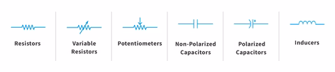
One of the first steps in reading an electrical schematic is understanding the different symbols used to represent system components, or at least having access to a schematic symbol cheat sheet. Some of the common symbols you’re likely to find on your schematic include:
Resistors: usually portrayed as zigzag lines with a terminal at each end. International symbols may represent resistors as a blank rectangle. Variable Resistors: a diagonal arrow intersecting the standard resistor zigzag symbol. Potentiometers: an arrow pointing to the zigzag resistor at a right angle stands for the potentiometer third terminal. Non-Polarized Capacitors: two lines perpendicular to the terminal plates Polarized Capacitors: two lines perpendicular to the plates, but one is curved to indicate the cathode. Inducers: a series of curved bumps or a looped coil. International schematics may use a filled-in rectangle.
Switches
Single-pole/single-throw switches appear on schematics as a half-connected line between the two terminals. Single-pole/double-throw switches have two actuator lines, and single-pole/triple throw switches have three.
For switches with multiple poles, a dotted line connects the switches on either side of the middle actuator.
Power and Voltage
Direct current, or DC, appears as a circle with a + and – symbol inside, while AC is represented as a circle containing a wavy line. For batteries, each cell is drawn as two lines perpendicular to the terminals, with a long line standing for battery’s positive terminals and the short line representing the negative.
Positive voltages appear as an arrow pointing up. Ground nodes are drawn as one to three flat lines, a downward-pointing triangle, or sometimes as a triangle.
Diodes, transistors, logic circuits, integrated circuits, and crystals all have their own symbols. Consult a symbol key to find their component symbols.
Names and Values
Symbols aren’t all you need to learn how to read an electric schematic drawing. Each symbol is assigned a name and value. The value will be the most important aspect of the part and may be expressed in ohms, farads, oscillating frequency, henries, or simply the name of the part chip.
Names are usually a combination of a letter and a number. The letter indicates the component type, while the number indicates multiple components of the same type are on the schematic. For instance, if a schematic has three capacitors, they will be labeled C1, C2, and C3.
Common Component Names:
- C: Capacitors
- D: Diodes
- L: Inductors
- Q: Transistors
- R: Resistors
- S: Switches
- U: Integrated Circuits
- Y: Crystals and Oscillators
How to Read Electrical Schematics
Practice is key to learning how to read electrical schematics. Start with simple schematics and work up to more complicated drawings. A schematic drawing shows the order of components wired on a circuit, with wires between components represented as lines. The completed circuit is known as a net. When wires connecting a terminal split into two or more directions, a junction is formed with a junction node represented as a small dot at the intersection. Nodes indicate all wires meeting at the junction is connected. In complex schematic drawings, entire nets may be given names and labeled as tags, rather than drawing the components within each net. This helps simplify large schematics. Large schematics may also be broken into function blocks, representing the system’s power input, regulation, connectors, or other system parts. Still confused about how to read electronic schematic drawings? TPC Training offers instructor-led training and online training on Electrical Ladder Drawings, Schematics and Diagrams. Learning how to read blueprints as well as schematic drawings increases your understanding of electrical machinery even more.